
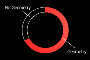
Unity comes out of the box with many user interface controls, but one thing that is lacking is a radial progress bar. I needed one for a project we are working on and contemplated my options. I could either pick up something on the asset store and spend time learning it, or I could make my own and “know how the sausage is made” so to speak. So I decided to make the sausage and decided to bring you along for the ride.
Many of the existing tools and tutorials to make radial progress bars use alpha tested shaders. Alpha tested shaders are fairly expensive on mobile GPUs and since I want this to run well in mobile VR, making it myself made the most sense. The alternative to alpha testing is to generate just the geometry you need and all empty space will not contain any geometry which means less time spent rendering that component.
 The script is relatively simple if you have ever written one that generates a mesh. Ultimately you need to generate a list of vertices for the geometry, indices list to define what the triangles are and optionally UV locations for the vertices. These values will then be used to create a Mesh object and get rendered through a MeshRenderer component.
First we need to create a class that contains all the variables we need to generate our progress bar. You will notice that I included RequireComponent attributes at the top of the class for MeshFilter and MeshRenderer. This is because we need these to actually see the object in the scene.
[RequireComponent(typeof(MeshFilter))]
[RequireComponent(typeof(MeshRenderer))]
public class CircleProgressBar : MonoBehaviour {

    public float StartAngle = 90.0f;
    public float InnerRadius = 0.1f;
    public float OuterRadius = 0.13f;
    public float Value = 1.0f;

    private float _radRes = 0.01f;

}
In order to generate the vertices, we need to brush up on some basic geometry; namely, how to calculate a point on a circle’s perimeter. Put simply, the x component is the radius multiplied by the sin of the angle and the y component is the radius multiplied by the cosine of the angle. Okay… maybe that wasn’t so simple, so for those of you that want to see what that looks like in code, here it is:
private Vector2 GetPointOnCircle(float radius, float radians)
{
    return new Vector2(
        radius * Mathf.Cos(radians),
        radius * Mathf.Sin(radians)
    );
}
With that out of the way, we can start making our method that generates the mesh. At a high level, we need to do a few things. First, we need to figure out how many segments our progress bar will be comprised of. In our instance, a segment is a quad of four points which creates two triangles. To do that we need to define a resolution (in radians) and divide the fill value by this number. Once we have that, we can create arrays for our vertices, UV coordinates, and triangles.
Now we can iterate through each segments and build the geometry of the arc. The first thing we need to do is calculate the inner and outer vertices at that specific segment angle. You may be asking why we aren’t generating four vertices for each segment since previously I mentioned a segment is made of four vertices. The reason is because we can use the vertices of the previous segment as our first two vertices and generate the last two.
Next we can generate UV coordinates. To keep this simple, we can just recycle the vertex information we created before. UV coordinates are made up of an array of Vector2 objects but our vertices are Vector3 objects. The way we are generating our vertex data, it will convert nicely. However, feel free to change the way the UV coordinates are generated for your needs.
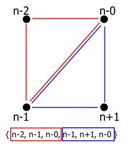
Lastly, we need to define our triangles. It always helps me to create a diagram to visualize how the triangle data needs to be organized. Below is a picture of one segment. The current segment’s vertices are on the right where the previous segment’s vertices are on the left. Each vertex is labeled with an n +/- the position in the array. I’ve also color coordinate the two triangles red and blue to help illustrate.
After all of that we just need to create the mesh with the information we just generated and assign it to the MeshFilter component. Below you will see I also defaulted the material on the MeshRenderer component. If you do not do that you will end up with the default magenta material.
    [ContextMenu("Generate Mesh")]
    private void GenerateMesh()
    {
        // Figure out how many segments this will render to
        int numSegments = Mathf.CeilToInt((2 * Value) / _radRes) + 1;

        // Create the vector, UV, and triangle arrays
        Vector3[] verts = new Vector3[numSegments * 2];
        Vector2[] uv = new Vector2[numSegments * 2];
        int[] tris = new int[numSegments * 3 * 2];

        // For each segment
        for (int seg = 0; seg < numSegments; seg++) { // Calculate the angle in radians for this segment float rad = seg * _radRes * Mathf.PI + (StartAngle * Mathf.Deg2Rad); // Calculate the points on the circle for this segment verts[seg * 2 + 0] = GetPointOnCircle(InnerRadius, rad); verts[seg * 2 + 1] = GetPointOnCircle(OuterRadius, rad); // Calculate the UV points for the vertices on this segment uv[seg * 2 + 0] = verts[seg * 2 + 0]; uv[seg * 2 + 1] = verts[seg * 2 + 1]; // If we are not the first loop through if (seg > 0)
            {
                // Create triangle data from this segment to the previous one
                tris[seg * 6 + 0] = seg * 2 - 2;
                tris[seg * 6 + 1] = seg * 2 - 1;
                tris[seg * 6 + 2] = seg * 2 - 0;
                tris[seg * 6 + 3] = seg * 2 - 1;
                tris[seg * 6 + 4] = seg * 2 + 1;
                tris[seg * 6 + 5] = seg * 2 - 0;
            }
        }

        // Create the new mesh
        Mesh m = new Mesh();
        m.vertices = verts;
        m.uv = uv;
        m.triangles = tris;

        // Set the mesh filter's mesh
        GetComponent().mesh = m;

        // Set the material
        GetComponent().sharedMaterial = new Material(Shader.Find("Standard"));
    }
You will also notice that I added the ContextMenu attribute at the top of the method. This is so that we have a convenient way to run this method while in the editor. This creates a menu item when you right-click the component in the inspector.
With all of that done, save out the script so we can add it to our scene. Once in the editor, create a new empty game object and name it “Circle Progress Bar”. Then, drag-and-drop the CircleProgressBar script onto the object. You will notice that the MeshFilter and MeshRenderer components were added alongside the CircleProgressBar script. This is because we added the RequireComponent attributes at the top of the class. Now you can right-click the component and select “Generate” for it to create the progress bar’s geometry.
And there you have it! A performant progress bar that doesn’t use any alpha-shading! Of course you will have to write some more code around the progress bar object to be able to update the geometry when the percentage changes, but now you can customize it to exactly how you need it to work. Now you know how the sausage is made! Don’t feel afraid to generate meshes in script now. It can save you a ton of time and even make your game perform better.
Let me know in the comments below if you have made this yourself or any other mesh-generating tools you have created in the past!
canada pharmacies online prescriptions https://social.acadri.org/read-blog/10065
Regards! Lots of stuff.